Contents
- Index
Impedance Measurements
This is a 2 channel transfer function measurement which gives excellent results for both the impedance magnitude and phase. The measurement will converge quickly. You will need a 1k ohm and a 10 ohm resistor.
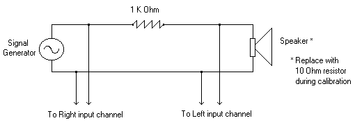
Setup the analyzer as shown in the screen shots below.
Step 1 - Calibrate to a 10 Ohm resistive load
Place a 10 Ohm reistor in place of the speaker in the diagram above.
Set the Signal Generator to "1 kHz tone"
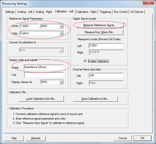
Go to the Calibration - Left Channel tab of of the processing settings
Press the "Measure Reference Signal" button
Go to the Calibration - Right Channel tab of of the processing settings
Now press the "Measure Reference Signal" button
Press Ok and close the processing settings dialog box.
Step 2 - Validate the calibration
(Leave the 10 Ohm resistor in the circuit)
Set the Signal Generator to "White Noise"
Run the analyzer - the Spectrum plot should have a flat line at 10 Ohms and the phase plot should be flat at 0 degrees.
Step 3 - Measure the speaker impedance
Remove the 10 Ohm resistor and connect the speaker or headset you wish to measure
Run the Analyzer
The Spectrum Plot shows the speaker impedance
The Phase Plot shows the speaker phase response
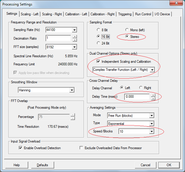
Main Analyzer Settings:
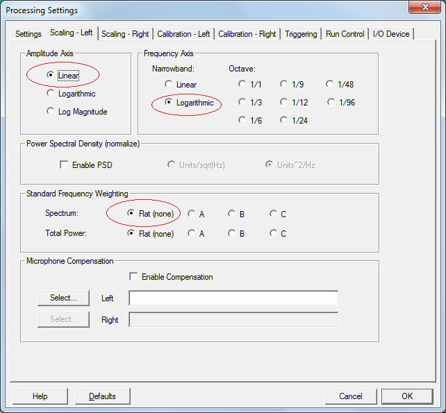
Scaling Settings - Both Channels:
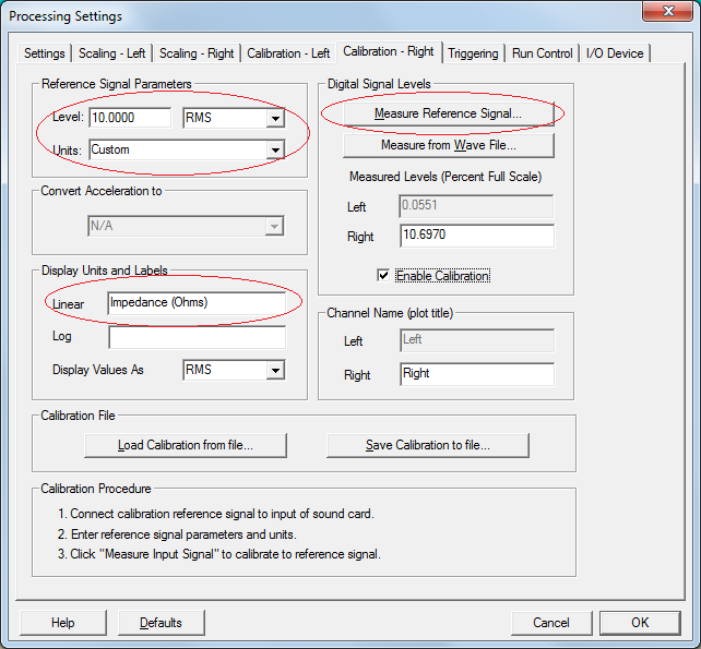
Calibration Settings - Left Channel:
Calibration Settings - Right Channel: